

What Is the Gear Connected to the Output, Such as a Wheel or Mechanism in a System. * UPDATED
What Is the Gear Connected to the Output, Such as a Wheel or Mechanism in a System. *
In this article, you will learn what is gear and how it works, types of gears and different types of gear trains.
Gears and Types of Gears
When there's a gear problem everything tin come to stop because of this it'southward important for you lot to understand how gears piece of work in gild to continue them working in their associated equipment operating.
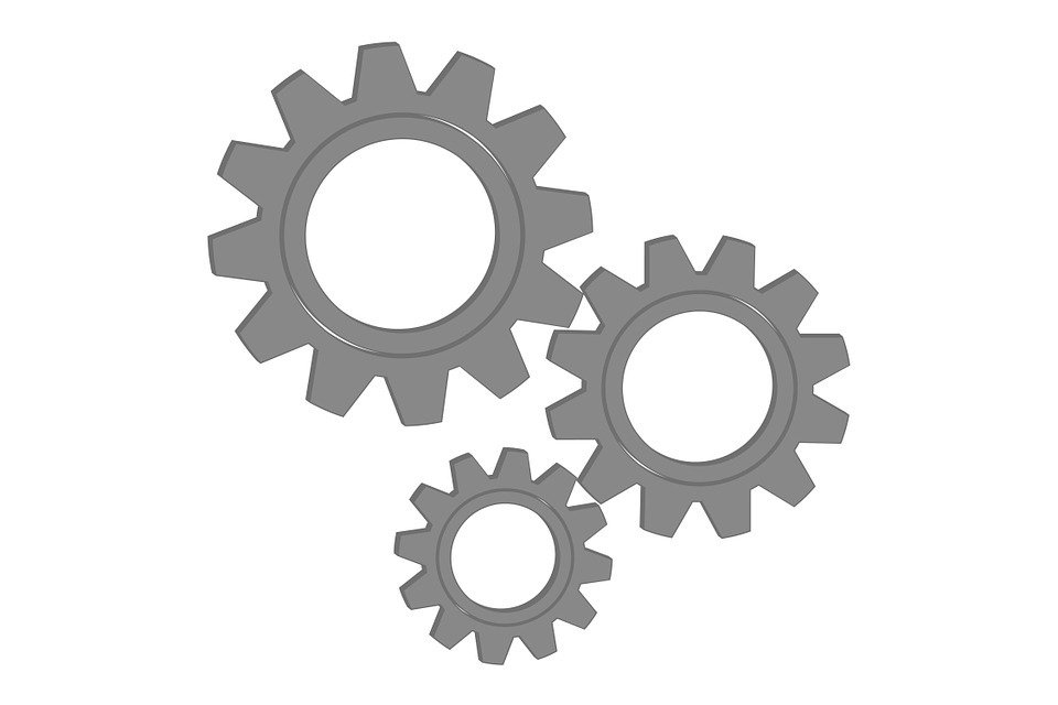
Gear can exist divers as a toothed wheel tin be engaged in another toothed wheel in order to transmit free energy that gives the alter of speed and management of motion. Information technology is widely used in mechanical devices. The teeth of the gear are mostly carved on wheels, cylinders or cones.
Many devices that we use in our mean solar day to day life have their own working principle. The molar and wheel of gear are working parts of all types of gears. The dissimilar types of gears are used to complete the transfer of energy in different means and dissimilar directions.
A gear is a component within a transmission device that transmits the rotational force to another gear or device. Gear is different from a pulley in that a gear is a round wheel which has teeth that mesh with other gear teeth. Allowing the force to exist fully transferred without slippage.
Depending on their construction and arrangement, geared devices tin transmit forces at dissimilar speeds, torques, or in a different direction, from the ability source.
The virtually common state of affairs is for a gear to mesh with some other gear. To overcome the problem of slippage equally in belt drives, gears are used which produce positive drive with compatible athwart velocity.
Read likewise: Gear Terminology: Basic Terms Used In Gear
Types of Gears
Following are the different types of gears:
- Parallel gears
- Spur Gears
- Helical Gears
- Double Helical or Herringbone Gears.
- Perpendicular axis gears
- Nonintersection perpendicular axis
- Intersection perpendicular axis gear
- Intersecting gears
- Screw gears
- Bevel Gears
- Not-intersecting and Non-Parallel gears.
- Worm Gears
- Rack and Pinion gears
Gears or toothed bicycle may exist classified according to the axes of the two shaft between which the motion is to the transmitted. The types of gears to be determined based on the awarding in which they are to be used.
1. Parallel Axis Gears
In this type of gearing, the axis of both the gears tends to be Parallel to each other. The types of gears that come under this system is gears are:
- Spur Gears
- Helical Gears
- Double Helical or Herringbone Gears.
Application of Parallel Axis Gears
Some typical application areas of spur and helical are automobile gearboxes, industrial gearboxes, etc. Some of the awarding areas of herringbone gears are in the gearboxes used for steel rolling mills, etc.
2. Perpendicular Axis Gears
In this type of gearing the axis of the gears tend to be perpendicular to each other. In that location are two in this type of gearing also. they are:
- Nonintersection perpendicular axis
- Intersection perpendicular axis gear
1. Nonintersection Perpendicular Axis
In this type, the two perpendicular axes of the gearing do not intersect each other. The ii types of gearing that fall into this category are Worm Gear and hypoid Gear.
Some typical applications of the worm gears are in the passenger lifts used in the buildings. Another typical application of the Hypoid gear is in the rear beam of the busses, lorries and heavy vehicles.
2. Intersection Perpendicular Axis Gear
In this type, the perpendicular axis of the gears tends to intersect at a certain point. The types of gears that fall under are the straight Bevel Gear, spiral bevel Gears, and Gears. some typical application of directly bevel gear is the differential machinery in the car.
Read too: What Is Gear Ratio And How To Calculate Gear Ratio
Classification of Gears
The different types of gears are classified every bit follows:
- Spur gear: for parallel axes shafts
- Helical gears: For both parallel and non-parallel and not-intersecting axes shafts.
- Spiral gears: For non-parallel and intersecting axes shaft.
- Bevel gears: For intersecting axes shaft
- Worm gear: For not-parallel and not-coplanar axes shaft
- Rack and pinion: For converting rotary motion into linear motion
1. Spur Gear
The spur gear is the most common and simplest type of gear. It is by and large used for manual of rotary motion between parallel shaft. The spur gear is the best option for gears except when speed, loads, and ratios direct towards other options.
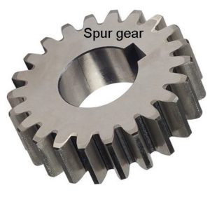
They accept straight teeth and are mounted on parallel shafts. Their general course is a cylinder or deejay. The teeth project radially, and with these "direct-cut gears". When 2 spur gears dissimilar sizes mesh together, the larger gear is called a wheel and the smaller gear is called a pinion.
In a unproblematic gear train of two spur gears, the input movement and force are applied to the commuter gear. The driver gear rotates the driven gear without slipping.
Read also: Concatenation Drives and Types Of Chains
2. Helical Gears
Helical gears offer a refinement over spur gears. The teeth of a helical gear are non parallel to the axis of rotation simply are ready at a helix angle. Helical gears can be meshed in a parallel or crossed orientation.
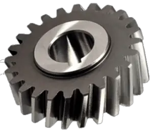
Forth with parallel helical gear, each pair of teeth get-go contacts one bespeak on the one side of the gear wheel. A moving curve of contact increases gradually confronting the teeth face to a maximum then come up back until the teeth accomplish contact at one signal on the opposite side.
Because of angled teeth of helical gear they reduce the dissonance and stress in the gears, most of the gears in your motorcar are helical. The use of helical gears is indicated when the awarding involves high speeds, large power transmission, or where no dissonance is important.
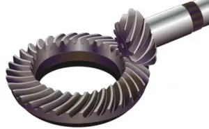
3. Bevel Gears
Bevel gears have teeth cut on a cone instead of a cylinder blank. they are used in pairs to transmit rotary motion and torque where the bevel gear shaft are at correct angles (90 degrees) to each other. When two bevel gear has their axes at correct angles and is equal sizes, they are called mitre gears.
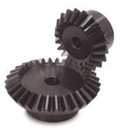
Bevel gear transmits power betwixt ii intersecting shafts at whatever angle or non-intersecting shaft. they are classified equally straight and screw tooth bevel and hypoid gears. These are gears cut from conical blanks and connect intersecting shaft axes.
The connecting shaft is generally at 90°and sometimes i shaft drives a bevel gear which is mounted on a through the shaft resulting in two output shafts. The bespeak of intersection of the shaft is called the apex and the teeth if the two gears converge at the apex.
Read also: Transmission Of Power By Rope Drive and [Types of Ropes]
iv. Rack and Pinion
A rack and pinion is a pair of gears which convert rotational movement into linear movement and vice versa. A circular gear chosen "the pinion" engages teeth on a linear "gear" bar called "the rack".
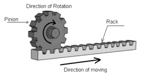
Rotational move applied to the pinion volition cause the rack to move to the side, upwards to the limit of its travel. The diameter of the gear determines the speed that the rack moves equally the pinion turns.
A rack and pinion are commonly establish in the steering mechanism of cars or other wheeled, steered vehicles. In a rack railway, the rotation of a pinion mounted on a locomotive or a railcar engages a rack between the track and pulls a train along a steep gradient, machine tools such as lathe motorcar, drilling motorcar, planning machine.
5. Hypoid Gear
Hypoid gear looks like the screw bevel gear in some respects. For example, hypoid gears are shaped like spiral bevel gears and high points are used on cross axis shafts like bevel gear sets are.
Simply different bevel gear sets the shafts of hypoid gears do not line up with each other they're starting time. This offset allows hypoid pinions to have as few as five teeth in a high ratio gear set up while the various types of bevel gears typically don't have less than x teeth on opinion
The smaller number of teeth on a hypoid pinion means that larger ratios tin be obtained with a hypoid gear ready than with a bevel gear set of the aforementioned dimensions.
6. Worm and Worm Bicycle
The arrangement of gears shown in the image is chosen a worm and worm wheel. The two elements called the worm screw and worm wheel.
A gear which has one tooth is called a worm cycle. The tooth in the form of a screw thread is chosen worm screw. The worm wheel is a helical gear with teeth inclined then that they can appoint with the thread-similar worm.
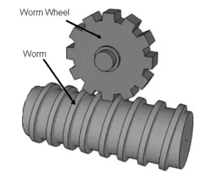
This wheel transmits torque and rotary motion through a correct bending. The worm can easily turn the gear, simply the gear cannot turn the worm. This is because of the angle on the worm is so shallow that the gear tries to spin it. Worm mechanisms are very quiet running.
It is used to transmit power between the driving shaft having their axes at right angles and non-coplanar equally shown in fig. Worm gears are used in machine tools when big gear reductions are needed.
Information technology is common for worm gears to accept reductions of xx:1, and fifty-fifty upwards to 300:i or greater. This feature is useful for machines such as conveyor systems, in which the locking feature can deed as a brake for the conveyor when the motor is non turning.
Types of Gear Trains
A gear train is a mechanical system formed by mounting gears on a frame. As mentioned above, when two or more gears mesh together to transmit ability from one shaft to another such arrangement is called a gear set or a gear train.
Sometimes ii or more gears are made to mesh with each other to transmit ability from ane shaft to another such a combination is chosen "gear train of the wheel".
Likewise, each gear is mostly attached to a shaft oftentimes gears that are meshed together will exist of different sizes in this instance the smaller gear is referred to as the pinion and the larger one is simply referred to as the gear.
Following are the different types of gear trains:
- Simple gear train
- Compound gear trains
- Reverted gear trains
- Epicyclic gear trains
1. Simple Gear Trains
In these types of gear trains, the distance between the ii wheels is great the movement from ane wheel to another is transmitted by providing one or more intermediate wheels as shown in the effigy.
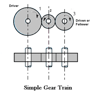
When the number of intermediate wheels is odd, the move of driver and follower is like every bit shown in the figure. If the number of intermediate wheels is even the move of the follower will exist in the opposite direction of the driver as shown in the figure.
2. Compound Gear Train
In compound gear train, each intermediate shaft has 2 wheels fixed to it. These wheels have the same speed. One cycle gears with the drier and the other bike gears with the follower fastened to the side by side shaft.
3. Reverted Gear Trains
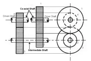
When the axes of the first and last wheels are co-axial the train is known equally "reverted gear trains" as shown fig. Since the movement of the first and last wheel is alike, therefore a compound wheel is provided. Since the altitude between the centres of the shaft 1 and 2 too as 3 and 4 is the same.
An epicyclic gear train, the axes of the shaft, over which the gears are mounted, move relative to a fixed axis. A elementary epicyclic or planetary gear train is shown the figure.
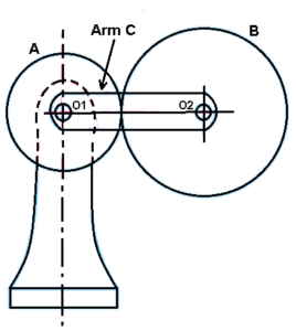
Here bike A and arm C accept a common axis at O1 about which they can rotate. The wheel B meshes with bike A and has its axis on the arm at O2, almost which the wheel B can rotate. If wheel A is fixed and the arm is rotated, the train becomes an "epicyclic gear train".
Download Pdf of this article

Determination
And then now, nosotros hope that we have clear all your doubts well-nigh Types of Gear Trains. If yous have still whatsoever doubts nigh the "Types of Gears" you tin can contact united states of america or ask in the comments.
We have likewise a Facebook community for you lot guys. If you want, you can join our community, here is the link to our Facebook grouping.
That'southward information technology cheers for reading. If you lot similar our article then please share information technology with your friends. If yous accept whatever questions well-nigh whatsoever topic you lot can ask in the annotate section.
Subscribe to our newsletter to get notified when we upload new posts.
Read Side by side:
DOWNLOAD HERE
What Is the Gear Connected to the Output, Such as a Wheel or Mechanism in a System. * UPDATED
Posted by: chrissoombeark1939.blogspot.com

Comments
Post a Comment